These are the basic for installing and testing CANFDuino support for the Arduino IDE, running and successfully testing your first CAN sketch.
Step 1 – Software Install & Download
Make sure you have the Arduino IDE installed, this was tested with 1.81. Download the CANFDuino folder zipped from the GitHub repository.
Step 2 – Putting the Files In the Right Place
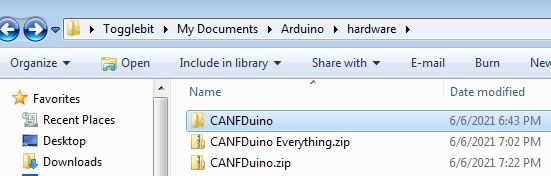
Close the Arduino IDE if you have it open. Unzip the folder and copy the whole folder to your local Arduino hardware folder. The path for this hardware folder is: C:\Users\YOUR USERNAME\Documents\Arduino\hardware. The whole folder should be pasted directly into the hardware folder creating: C:\Users\YOUR USERNAME\Documents\Arduino\hardware\CANFDuino. If you do not have a hardware folder, create one and place CANFDuino folder inside of it.
Step 3 – Set the Target Board
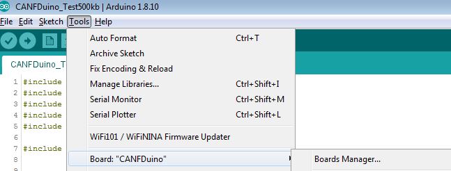
Open the Arduino IDE, Go to the “Tools->Board->CANFDuino” to select the CANFDuino board as your target board. If it is not there, step 2 wasn’t done correctly.
Step 4 – Install Board Support
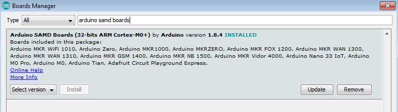
Go to Tools->Board->-Boards Manager-Wait for the downloads to finish. Click on “Arduino SAMD Boards (32-bits ARM Cortex-M3), including Arduino M0” and Install. This can take a while to download if you don’t already have the library.
Step 5 – Load Example Code
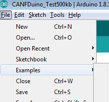
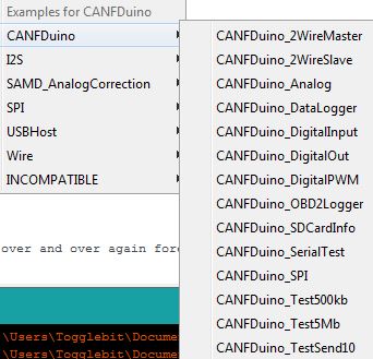
Go to File->Examples->CANFDuino->CANFDuino_Test500Kb.ino (have a look at all the other examples as well)
Step 6 – Wire It Up
Wire the CANbus DB9 connectors or jump the 2pin headers on the PCB to connect CAN0 bus to the CAN1 bus.
Connect CAN0 High to CAN1 High, CAN1 Low to CAN1 Low. See hookup guide for details
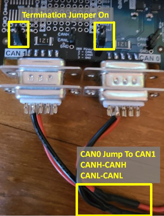
Step 7 – Don’t Forget Termination
Jumper at least one of the two termination resistors on the PCB enabling termination resistors on the bus. (two ideally) See hookup guide for details
Step 8 – Install FTDI drivers
Connect USB cable to CANFDuino and the PC, this will power the unit an prompt for a driver install. Wait for the driver to install if needed (one option is to skip obtaining from windows and selecting the driver in the hardware\samd\drivers folder). Go to Tools->Port and select the COMM port that is labeled CANFDuino. You may need to shut down the IDE and re-open it after installing the driver. If it doesn’t work, use FTDI exe in the GitHub CDM212364_Setup.zip repository to install the driver, then repeat step 8.
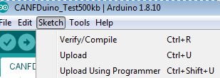
Step 9 – Build it, Flash It
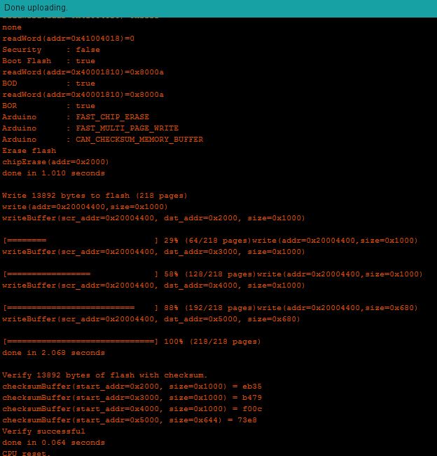
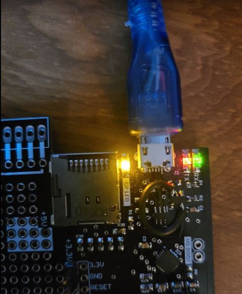
Go to Sketch->Upload. After compiling the IDE will send a signal to the CANFDuino to enter the bootloader. Note when the unit is bootloading the orange LED will stay on and strobe off quickly for 1-2 seconds. This occurs anytime the processor is reset (initial power on, or serial terminal is opened up etc). You should see the green/red comms LED’s flicker during sketch upload and you will know it’s getting flashed properly.
Step 10 – Open The Monitor
Go to Tools->Serial Monitor, note that this will also cause entry into bootloader for about 4-5 seconds before the sketch runs (for permanent code/bootloader bypass there is a jumper on the PCB). Baud rate should be 115200.
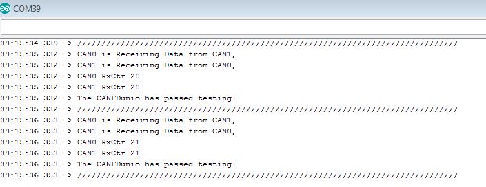
Step 11 – See If It Works
See diagnostic printout in the comms window indicating pass/fail of testing. The number of packets recieved by CAN0 and CAN1 should be incrementing by 1 for each printout. If it is 0, there is a problem, typically the cause of failure is improper wiring or no termination resistor.